Lining
Preliminary operation for using the niveau de dévers method with the ground plan.
Definitions
- Lining: tracing, on two adjacent faces of a irregular timber, the projections of a line chosen to be the timber's axis.
- Counter lining: projecting those lines onto the two opposing faces of the timber.
- Square line (trait carré): line perpendicular to a given line.
- pièce de niveau: timber that has been leveled along its length.
- pièce de dévers: timber that has been leveled across its width i.e., has no twist.
- Reference area (plumée): small rectangular area on a surface which has been dressed (planed) smooth, [ so that a level can be accurately placed on it]. This serves as a reference for lining and counter lining.
- to plumb: to trace a vertical line from a point by using a plumb line.
Step 1
Block up the timber so that its flattest face (abcd) is level lengthwise.Step 2
Make a reference area in the middle of the face abcd at mnoq.Step 3
From X at the middle of ab and X' at the middle of cd, draw the line XX'.Step 4
Draw a perpendicular to XX' in the reference area.Step 5
Turn the timber 90 degrees so that face abcd is vertical and face adef is horizontal.Step 6
Make a reference area nqpr in the middle of face adef.Step 7
With Y at the middle of the line af and Y' at the middle of line de, draw the line YY'Step 8
Draw a perpendicular to YY' in the reference area that intersects point u. [u is the intersection of the perpendicular drawn in face adef's reference area with the edge of the timber.] This perpendicular intersects YY' at k'.Step 9
Make line k'u level across the width of the timber. [The semi-circular object in the drawing is a plumb level.]Step 10
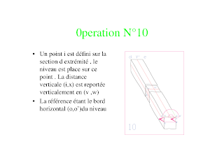
- Choose a point i on the end of the timber. The plumb level is placed on this point. The vertical distance iX is transferred [across the face] to vw.
- [Draw Xw.]
- The reference is the horizontal edge of the plumb level, oo'.
Step 11
- At the other end of the timber, choose a point i1 and perform the same operation. The plumb level is placed on i1 and the vertical distance i1X is transferred to v1w1. The horizontal edge of the plumb level is still used as a reference.
- Draw line ww1.
Step 12
On the near face, put a plumb line against point Y. This defines point g on the line Xw and point t on the bottom face.Step 13
- On the far face, put the plumb line against point Y' and mark point g' on the line X'w' and t' on the bottom face.
- Draw line tt' on the bottom face [(after turning the timber so you can do this operation)].
Step 14, the final result
- The four lines XX', YY', ww' and tt' represent the projections of the timber's axis onto the four faces.
- The axis passes through gg'.
Conclusion
The timber can now be aligned on the ground plan.This procedure is directly applicable to assemblies in which the timbers' orientations are square to each other, like in roof trusses. In the previous post in the series on the French scribe method, we skipped directly to the "good stuff" of laying out timbers with twisted orientations. The lining procedure is still useful in that case too. Our example was the layout of a hip rafter and king post. The king post will also be layed out with rafters, so it will be lined in the manner described here. That establishes a central axis, seen here:
at the intersection of the green lines. The reference plane common to the hip rafter and king post will pass through that axis. Once we have the king post twisted to the correct orientation, we can use the plumb level to draw a level line through the central axis on both end faces of the timber. We then connect those to make the reference assembly lines that represent the reference plane.Note: I found many translations of French carpentry terms at Marc Guilhemjouan's pages on traditional timber frame techniques.


